
Assembly manual
Open the guide-
Step 01
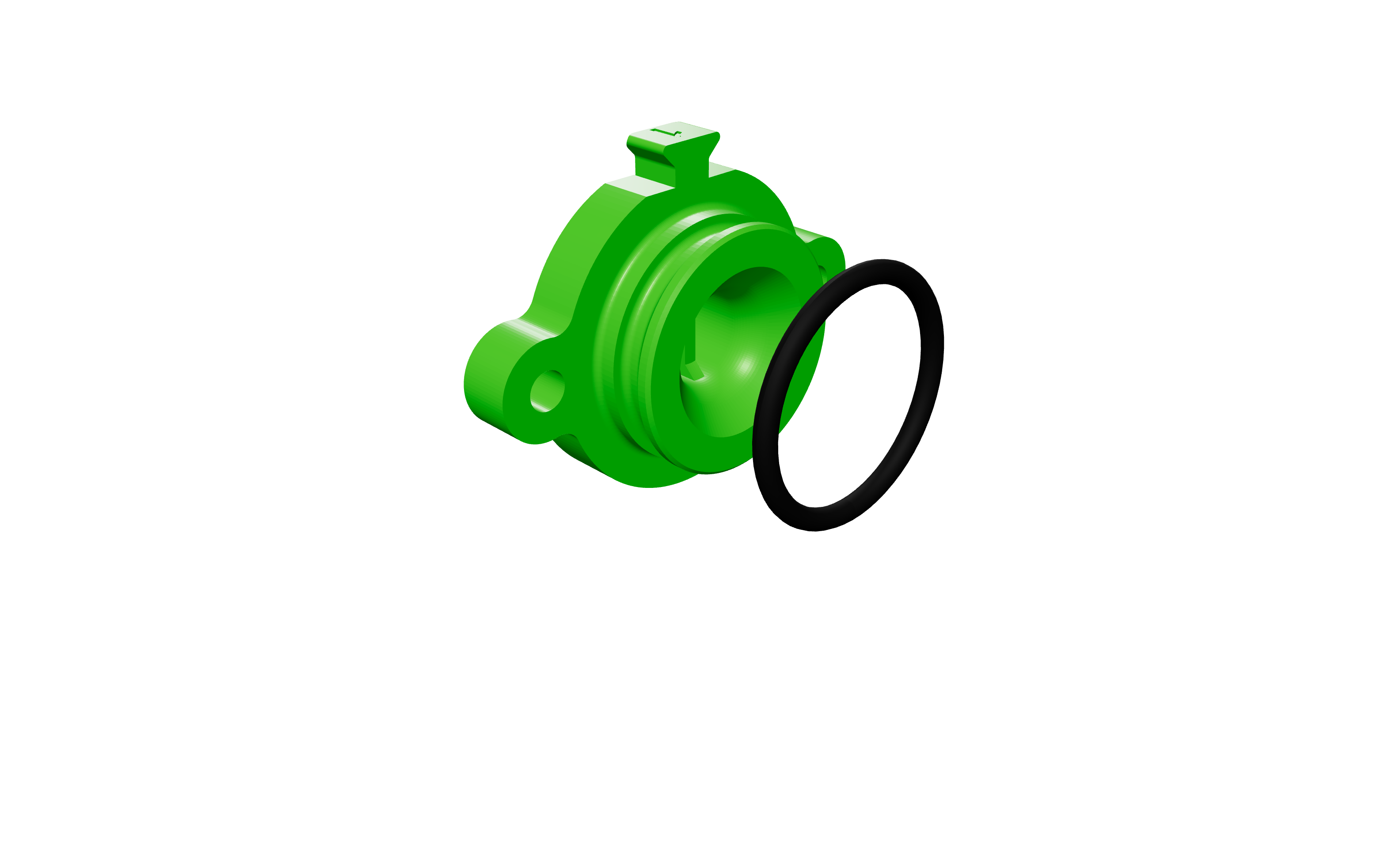
Put one of the larger o-rings (Dash 123 o-ring) onto the rear side of the PTsealer.
Printed parts
- 1 ptsealer
Hardware
- 1 29×3 O-ring
-

Step 02
NO GLUE on this large o-ring.
Printed parts
- 1 ptsealer
Hardware
- 1 29×3 O-ring
-

Step 03
Glue one of the Dash 016 o-rings onto the front of the PTsealer, inside the groove. Apply 4 dots of super glue into the groove, then place the o-ring in the groove. Hold the o-ring in place while the glue dries.
Printed parts
- 1 ptsealer
Hardware
- 1 29×3 O-ring
- 1 15.6×1.78 O-ring
-
Step 04
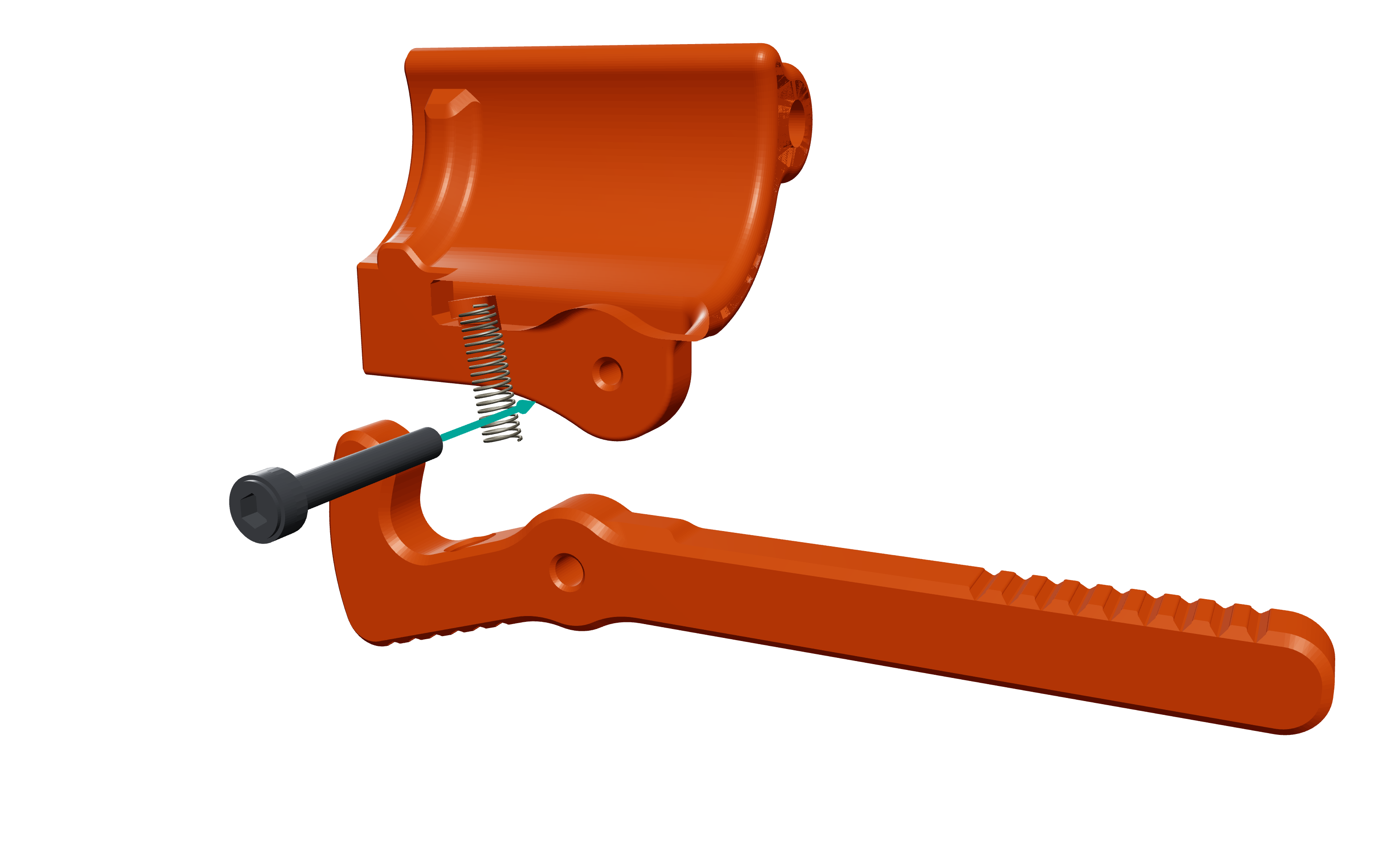
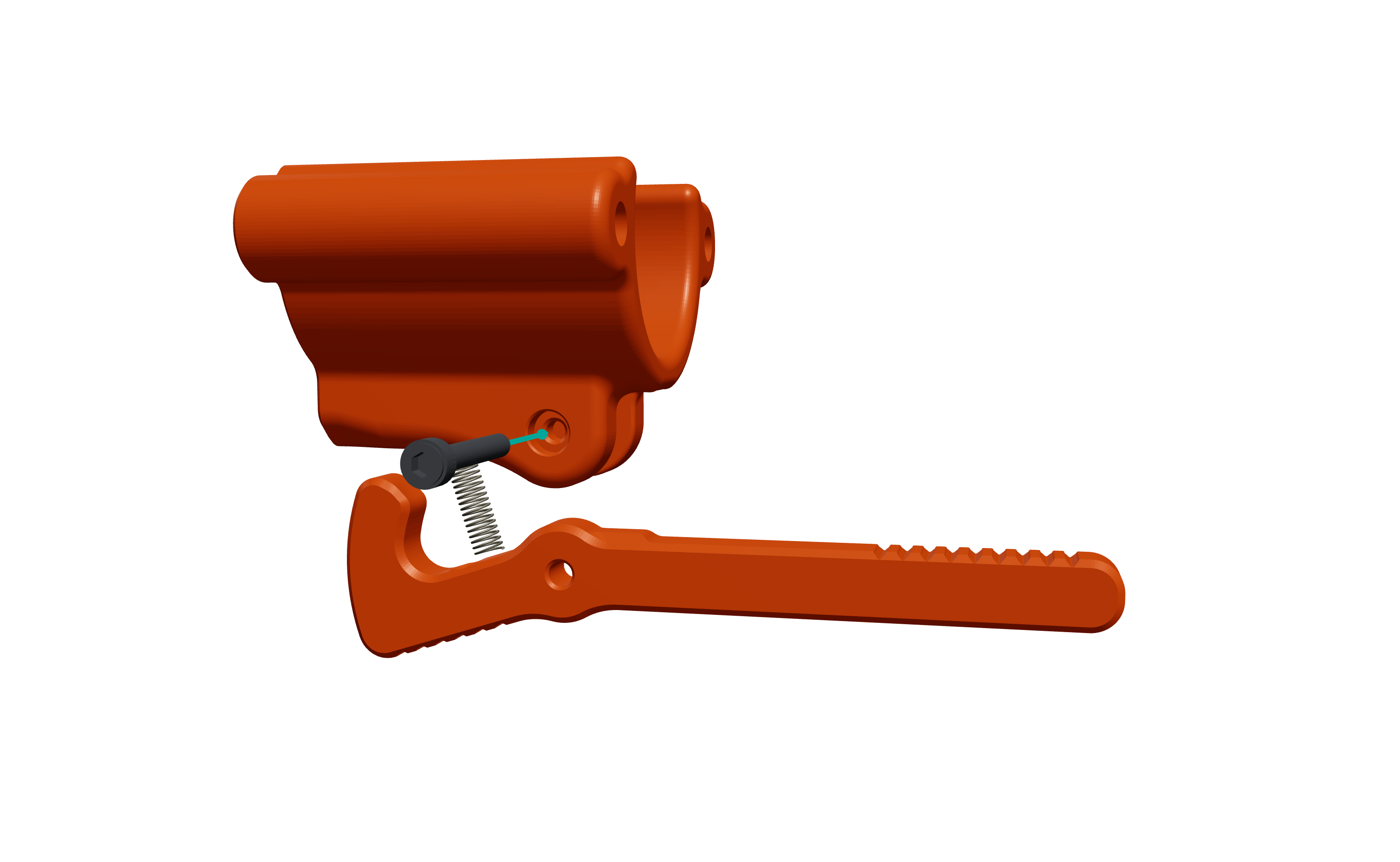
Install the Ejector lever into the Shell Carriage
Printed parts
- 1 shellcarriage_withejector
- 1 ejector_frontleverversion
Hardware
- 1 M3×20 SHCS
- 1 4.57×0.36×15.88 spring
-
Step 05
Line up the small spring with the hole on the inside of the Carriage. (There is a small tab inside the hole to help hold the spring in place during assembly.)
Printed parts
- 1 shellcarriage_withejector
- 1 ejector_frontleverversion
Hardware
- 1 M3×20 SHCS
- 1 4.57×0.36×15.88 spring
-
Step 06
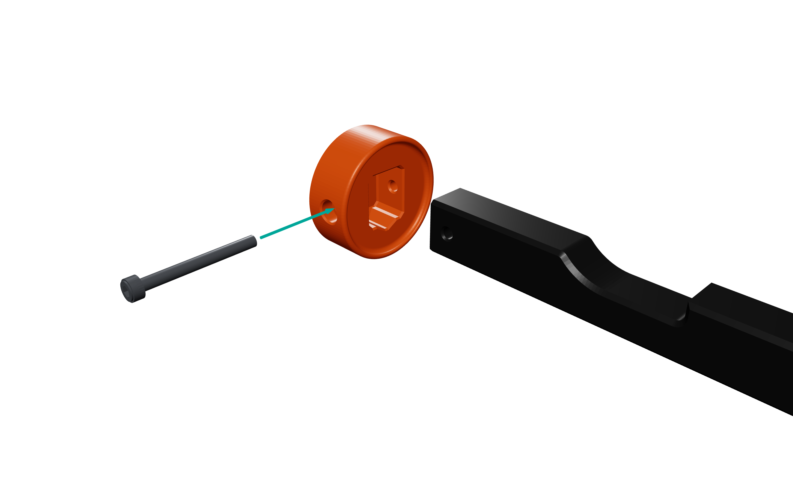
Insert the Plunger Rod into the rear of Plunger Head B. Secure with an M3x30 screw.
Printed parts
- 1 plungerhead_b
- 1 plungerrod
Hardware
- 1 M3×30 SHCS
-
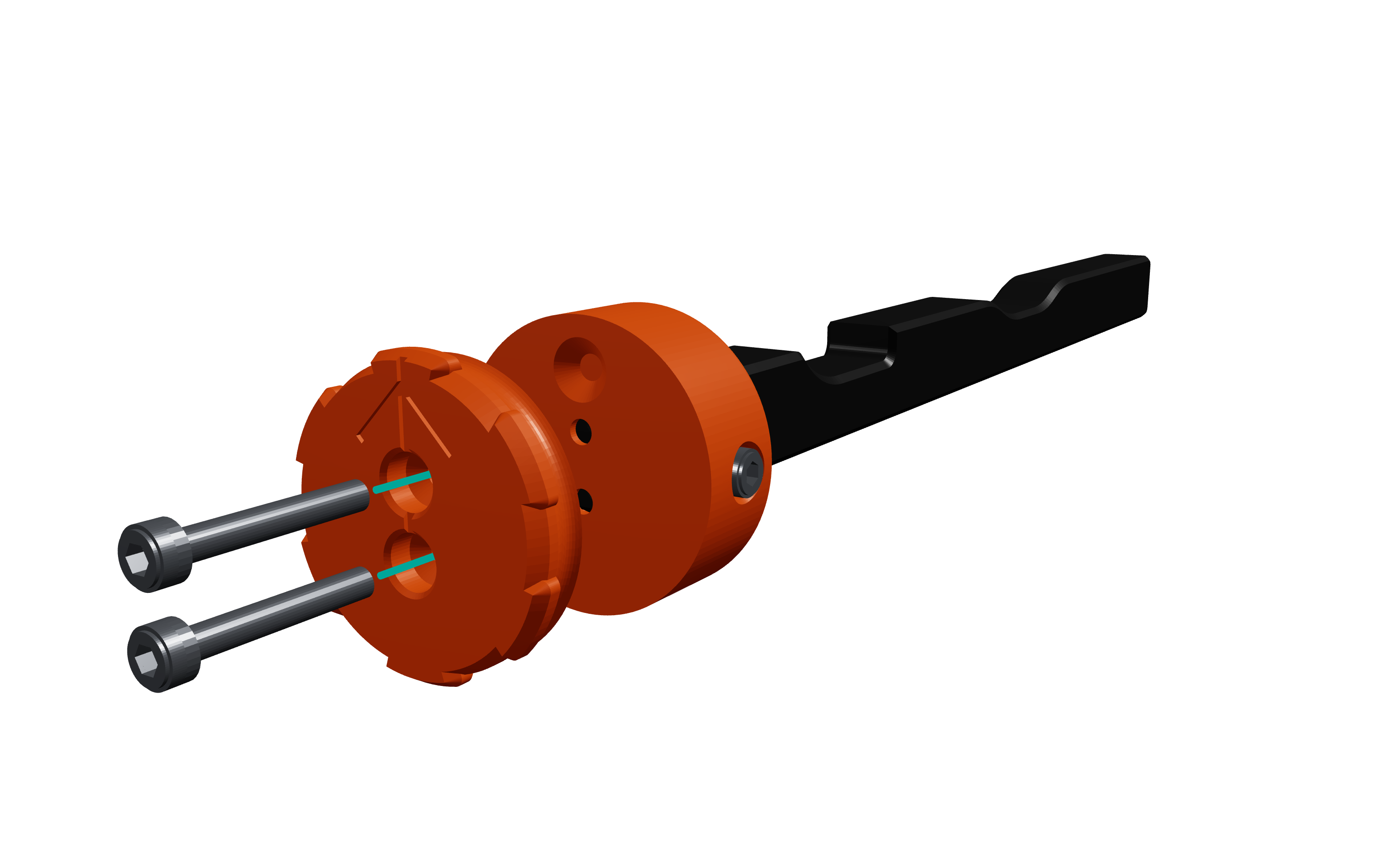
Step 07
Line up Plunger Head A with Plunger Head B, using the small top divot as a guide. Drive 2x M3x20 screws through Plunger Head A into B, and through the Plunger Rod until tight.
Printed parts
- 1 plungerhead_b
- 1 plungerrod
- 1 plungerhead_a
Hardware
- 1 M3×30 SHCS
- 2 M3×20 SHCS
-
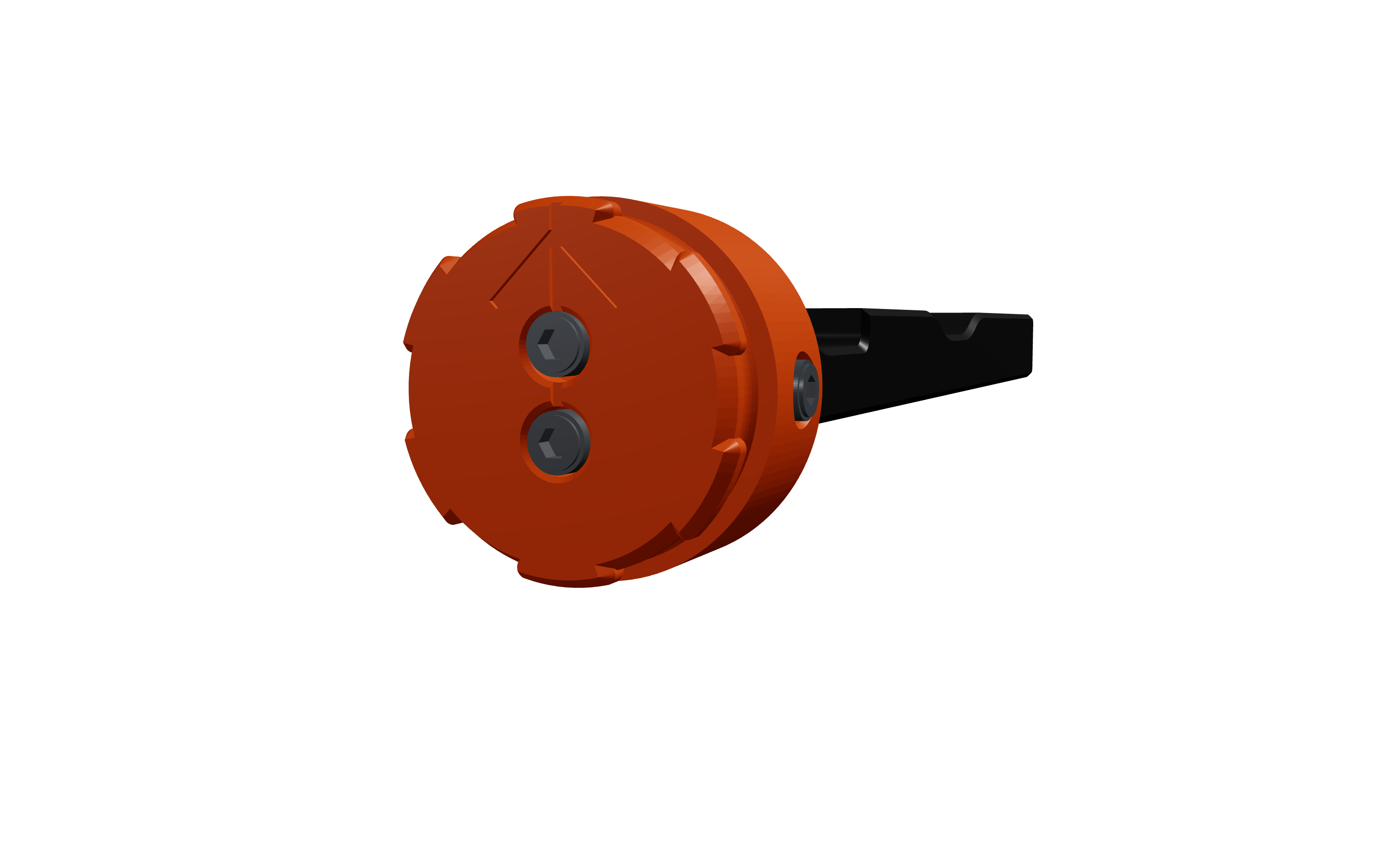
Step 08
Remove the backing from the adhesive plunger padding. Press the padding firmly onto the face of the plunger, keeping it centered while doing so.
Printed parts
- 1 plungerhead_b
- 1 plungerrod
- 1 plungerhead_a
Hardware
- 1 M3×30 SHCS
- 2 M3×20 SHCS
-
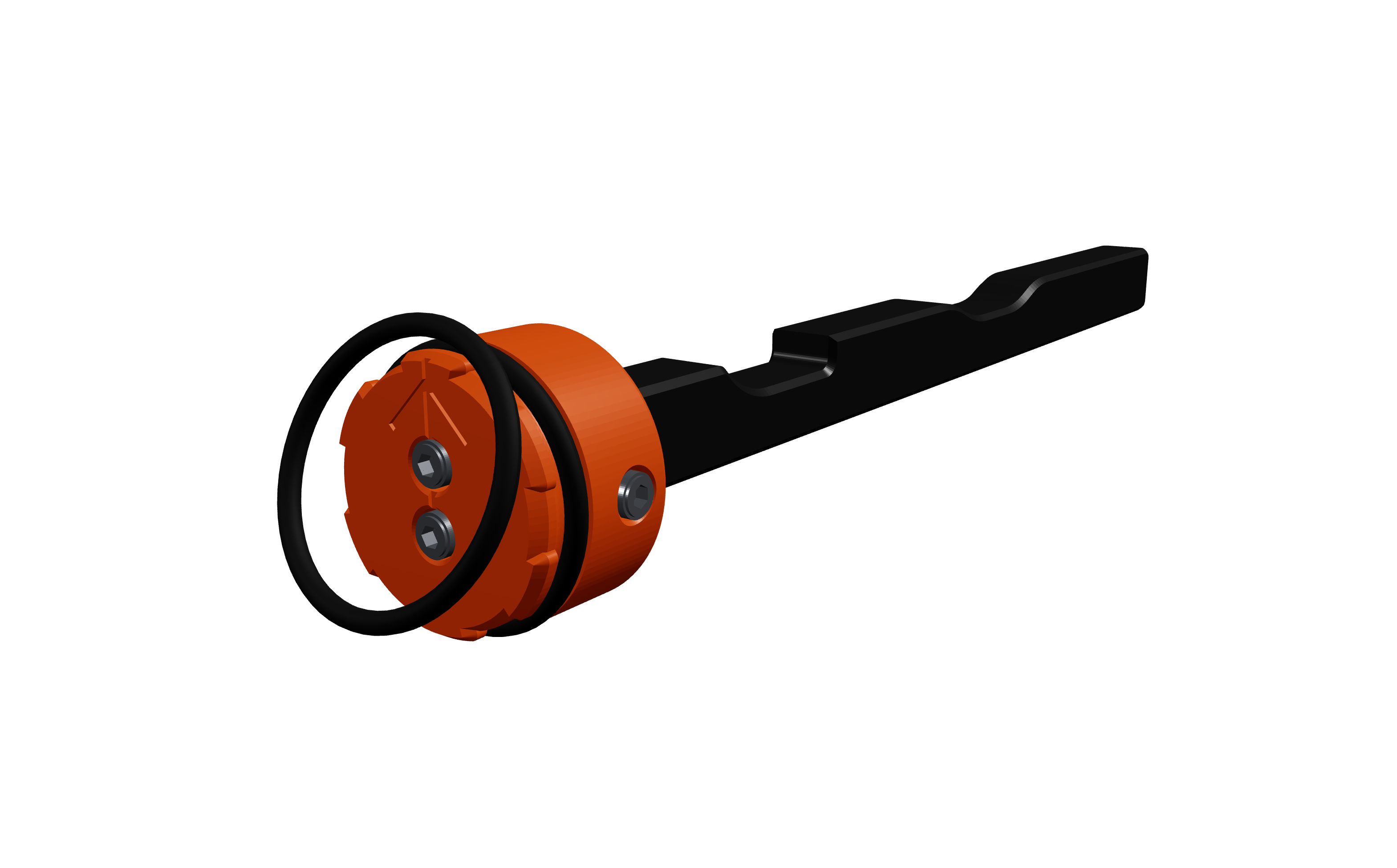
Step 09
Push one of the larger o-rings (Dash 123 o-ring) over the plunger head until it sits in the groove
Printed parts
- 1 plungerhead_b
- 1 plungerrod
- 1 plungerhead_a
Hardware
- 1 M3×30 SHCS
- 2 M3×20 SHCS
- 2 29.82×2.62 O-ring
-
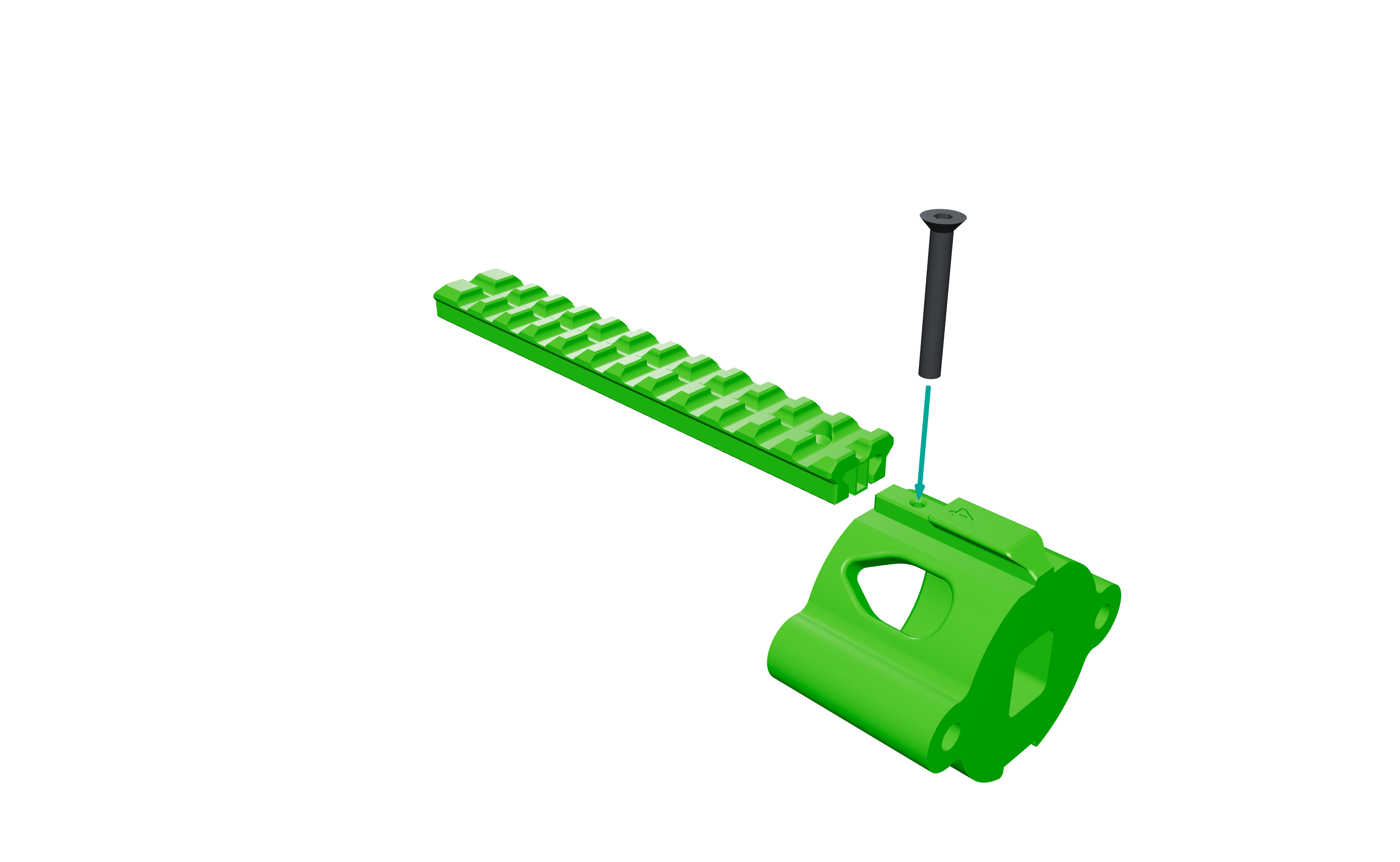
Step 10
springcup
Printed parts
- 1 springcup
- 1 rail_a
Hardware
- 1 M4×30 FHCS